
Overview
Walk into most composite engineering teams and you will find two separate worlds: the designers who live in CATIA, building ply stacks and laminate sequences, and the analysts who rebuild those structures in a separate FEA environment, translating intent into simulation geometry. The gap between those two worlds is not just inefficient. It is where accuracy goes to die.
A designer defines a stack-up in CATIA. An analyst re-creates it from a drawing, using assumed fiber orientations and simplified material cards. The model runs. The analyst reports results. Nobody is quite sure whether those results represent the design that was actually defined, or a reasonable approximation of it.
This article is about closing that gap, and the specific tools that make it possible.
The building-block problem in composite certification
Composite certification follows what the industry calls the building block approach - a pyramid of tests that starts at the material coupon level and works up through subcomponents, components, and finally the full structure. It is rigorous. It is also expensive and slow.
The promise of integrated simulation is not to eliminate this pyramid. Regulatory bodies like EASA and the FAA still require physical evidence. What simulation can do is compress the middle layers: reduce the number of physical sub-element and component tests by replacing them with well-validated virtual ones, and make the physical tests that do run more targeted and informative.
How CATIA and Abaqus actually talk to each other
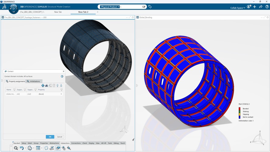
The 3DEXPERIENCE platform creates a native connection between CATIA Composites Design and Abaqus: not through a file export, but through a shared data model. That distinction matters enormously in practice.
In the traditional workflow, passing data from CATIA to an FEA tool involves exporting a neutral file format (IGES, STEP, or a proprietary exchange format), stripping most of the composites metadata in the process, and rebuilding the laminate definition manually in the solver environment. Orientations drift. Material cards do not fully transfer. Someone makes decisions along the way that silently change the model.
Three approaches to composite definition in CATIA
The CATIA Composites Design application supports three approaches to defining composites, and Abaqus can consume all three representations directly on 3DEXPERIENCE:
- Ply-by-ply: Each ply is explicitly defined with a contour, material, fiber orientation, and stagger offset. This gives the finest control over the laminate and is preferred for complex aerostructures where every ply boundary matters.
- Zone-based: Laminate zones are defined first (each zone carrying a thickness law or stacking sequence), from which individual plies are then generated automatically. This is efficient for large structures with gradual thickness transitions.
- Grid-based: Stacking sequences are managed via a grid or spreadsheet-like interface. Useful for very large structures where many zone-to-ply permutations need to be managed systematically.
Approaches to modelling damage in Abaqus: the big picture
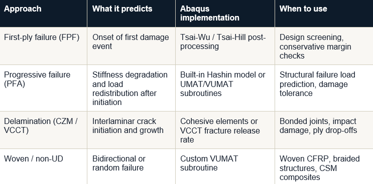
Before diving into any specific failure criterion, it is worth stepping back. Damage modelling in composite FEA is not a single technique. It is a layered set of approaches, and choosing the right one depends on what you are trying to predict and at what level of fidelity. Abaqus provides tools across all of these levels.
Level 1: First-ply failure (FPF) using failure indices
The simplest approach to composite failure is to apply a failure criterion as a post-processing check on a linear elastic stress state. You run a standard linear static analysis, extract the ply-level stresses, and evaluate whether any ply exceeds a defined failure surface. No material degradation is modelled. The structure is assumed to carry load as if undamaged throughout.
This is known as first-ply failure analysis. It tells you the load at which the first damage event is predicted, and which ply and mode is responsible. Criteria commonly used in this way in Abaqus include:
- Maximum stress and maximum strain: Simple component-by-component checks. Conservative and easy to implement, but they do not capture the interaction between stress components.
- Tsai-Hill: An interaction-based polynomial criterion derived from the Hill yield criterion for anisotropic metals, adapted for composites. It accounts for stress interaction but does not distinguish between tensile and compressive failure.
- Tsai-Wu: A more general polynomial criterion that includes separate tensile and compressive strengths and a biaxial interaction term. Widely used in industry, though the interaction coefficient requires biaxial test data that is not always available.
Level 2: Progressive failure analysis (PFA)
Progressive failure analysis goes one step further. Rather than stopping at the first damage event, the material stiffness is degraded at each integration point where a failure criterion is met, and the load is redistributed to the surrounding structure. The analysis continues until global instability or a defined failure condition is reached.
This approach better represents the physical behaviour of composite laminates, which typically continue to carry load after initial matrix cracking. The result is a load-displacement curve that shows progressive stiffness loss rather than a single "safe / unsafe" threshold. PFA in Abaqus can be implemented in two main ways:
- Built-in Hashin damage model: Damage initiation is governed by Hashin's four in-plane failure modes (detailed in the next section). Once initiated, damage evolves according to an energy-based stiffness degradation law. This is the most accessible route for shell and continuum shell element models.
- User subroutines (UMAT, VUMAT, USDFLD): For solid (3D) elements, or for failure theories not built into Abaqus (such as Puck's action-plane criterion or the LaRC05 family), engineers implement PFA through Fortran-based subroutines. This requires more expertise but offers full control over the failure physics, including 3D Hashin variants, crack-band regularisation, and custom softening laws.
Level 3: Delamination and interlaminar failure
In-plane criteria like Hashin and Tsai-Wu do not capture delamination, which is a fundamentally different failure mode occurring at the interface between plies rather than within them. Delamination is governed by interlaminar stresses and fracture mechanics, not by ply-level strength values.
Abaqus provides two main approaches for delamination:
- Cohesive elements (CZM): Thin cohesive elements are placed at ply interfaces where delamination is expected. The traction-separation law (typically bilinear) governs damage initiation and evolution at the interface. The mixed-mode formulation by Camanho and Davila (2002), which Abaqus implements, is the reference approach for mode I / mode II / mode III coupling.
- Virtual Crack Closure Technique (VCCT): An energy-based approach that computes the strain energy release rate at an existing crack front and compares it to mode-specific fracture toughness values. VCCT is appropriate when a pre-existing crack or defect is known and its growth is to be tracked.
Level 4: Woven and non-UD composites
The failure criteria above are derived for unidirectional (UD) fiber-reinforced composites. Woven fabrics, braided textiles, and chopped strand mats have bidirectional or random fiber architectures that require different modelling approaches. Abaqus does not natively model woven composites, but the framework of user subroutines and material definition allows engineers to implement adapted criteria. Recent research has extended Hashin's framework to woven fabrics by adding bidirectional failure modes, with good correlation to experimental data in both quasi-static bending and high-velocity impact scenarios.
Hashin's criteria in depth: the built-in PFA model
Among the progressive failure approaches, Abaqus's built-in Hashin damage model is the most practical starting point for most composite structural analyses. It is worth understanding what it does and, critically, what it does not do.
The four failure modes
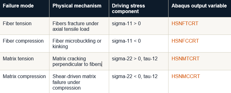
Hashin's key insight is that fiber-reinforced composites do not fail as a homogeneous material. They fail through four physically distinct mechanisms, each driven by a different stress state. The 1973 and 1980 formulations distinguish these modes explicitly:
From initiation to fracture: damage evolution
Damage initiation tells you where a composite starts to break. Damage evolution tells you what happens next - how material stiffness degrades as cracks propagate. Abaqus implements this through an energy-based softening model, where the rate of stiffness reduction after initiation is governed by the fracture energy associated with each damage mode (fiber or matrix, tension or compression).
This progressive failure capability is what separates a serious composite analysis from a simple first-ply failure check. Rather than a single safe or unsafe answer, you get a map of how failure initiates and spreads through the laminate under increasing load, information that directly informs both structural optimization and test program design.
Analysis types in the Composite Structures Analysis Engineer role
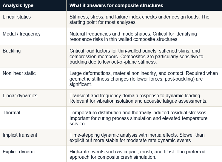
The Composite Structures Analysis Engineer role on 3DEXPERIENCE provides access to the full range of Abaqus analysis types. The table below summarises what is available and what it is most useful for in a composite context:
The workflow from concept to validated design
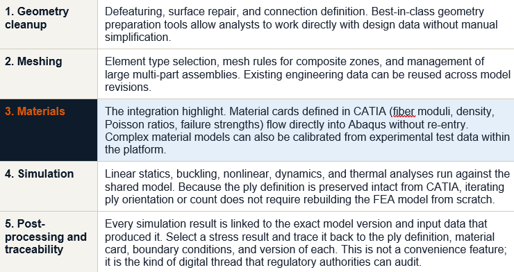
The Composite Structures Analysis Engineer role on 3DEXPERIENCE structures the analysis process into a coherent five-stage sequence, one that starts with geometry preparation and ends with traceable, signed-off results.
Iterating on ply design without restarting
One of the more practical payoffs of the integrated workflow is how quickly you can explore design alternatives. Because the ply definition in CATIA is directly connected to the simulation mesh, a change in fiber orientation, ply count, or stacking sequence can be reflected in a new simulation run without rebuilding the model from scratch.
Consider a common optimisation loop: a wing rib defined with a standard [0/+45/-45/90]s quasi-isotropic layup, run through a linear static analysis to check stiffness. The stiffness is adequate, but the first-ply failure index in bending is borderline. The designer adjusts the off-axis angle from 45 degrees to 35 degrees, recomputes the draping check in CATIA, and the analyst reruns the Abaqus job. Because the model is shared and not transferred, this loop takes hours rather than days.
Practical optimisation studies enabled by the integrated workflow
- Parametric ply orientation studies: Change angle plies across a range, evaluate stiffness and failure index response. Direct connection to CATIA means drapeability is checked in the same iteration, preventing orientations that are structurally attractive but physically unmanufacturable.
- Thickness tapering optimisation: Vary ply drop-off regions to find minimum weight configurations while satisfying buckling load factors and damage tolerance requirements.
- Load case coverage mapping: Run multiple load cases (manoeuvre, gust, ground, fatigue) and build a critical load envelope from which the most demanding combinations drive the laminate design.
Where this matters most: industry contexts
Aerospace
The drivers here are weight, certification, and damage tolerance. Composites now make up more than half of modern airliner structures by weight, and the certification evidence for those structures must be traceable, reproducible, and linkable to a specific configuration. The digital thread in 3DEXPERIENCE directly addresses the configuration management challenge that has historically made composite certification so document-intensive.
Automotive and motorsport
In high-performance automotive applications, particularly motorsport where structures are redesigned frequently and the simulation-to-physical-build cycle is compressed, the ability to run progressive failure analyses on impact scenarios without rebuilding models is commercially significant. Carbon fiber tubs, suspension components, and body panels all involve complex 3D stress states under crash loading that Abaqus explicit handles well.
Pressure vessels and energy
Type IV composite pressure vessels for compressed hydrogen storage represent one of the most demanding composite analysis problems: combined winding-induced residual stresses, pressure cycling fatigue, and liner-to-composite interface debonding. The Abaqus wound composite modeller (WCM) plugin allows dome geometry and helical winding parameters to be modelled accurately, which is critical for vessels where the dome zone failure governs burst pressure.
The practical case
If you are running a composite simulation workflow today that involves exporting from CATIA, re-creating laminate definitions in a separate preprocessor, and manually managing material data between design revisions, there is a better way to work, and it does not require abandoning your existing knowledge base.
The physics of composite failure are complex. Hashin's criteria, progressive damage evolution, cohesive zone delamination, these are not simplified concepts, and implementing them correctly requires engineering judgment. What the 3DEXPERIENCE workflow removes is the data-handling overhead that surrounds those engineering decisions, so analysts can spend more time on the mechanics and less on model plumbing.
Watch the full workflow demonstration from Brice Thivolle, Senior Solutions Consultant at Dassault Systemes, here:
Webinar: Master Composite Simulation in Abaqus: Tools Explained
References and further reading
Hashin, Z. and Rotem, A. (1973). A fatigue criterion for fiber-reinforced materials. Journal of Composite Materials, 7, 448-464.
Hashin, Z. (1980). Failure criteria for unidirectional fiber composites. Journal of Applied Mechanics, 47, 329-334.
Camanho, P.P. and Davila, C.G. (2002). Mixed-mode decohesion finite elements for composite delamination. NASA/TM-2002-211737.
Falzon, B.G. and Tan, W. (2017). Virtual testing of composite structures. In: The Structural Integrity of Carbon Fiber Composites. Springer, Cham.
Aerospace America / AIAA. The case for more virtual testing. aerospaceamerica.aiaa.org
Dassault Systemes. CATIA Composites Design 3 (CPD) product documentation. 3ds.com
Abaqus Documentation: Damage and failure for fiber-reinforced composites, overview. Simulia / MIT Engineering.
This blog was written by Melad Fahed for Launchtech, a Dassault Systemes simulation partner in the Middle East. Technical claims are based on referenced sources; simulation capability details reflect the 3DEXPERIENCE platform.
Author

Melad Fahed
Technical Director
Melad holds a Bachelor's and a Master's degree in Mechanical Engineering from Khalifa University. His expertise lies in Finite Element Analysis, parametric optimization, and additive manufacturing.