DELMIA · Industrial Engineering
Virtual Factory
Create and simulate a 3D virtual twin of your entire factory, from the layout of machines to work cells and production lines.
Download the DELMIA Virtual Factory datasheetsOne virtual twin
3D production system design and validation
The 3D layout, started from your 2D drawing
A catalog of parametric resources is snapped to your existing 2D factory drawing to quickly realize the 3D layout. Layout objects are positioned, aligned and snapped with simplified tools, so a planner who is new to CAD defines the plant layout efficiently.
The whole line, running
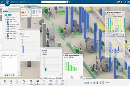
Factory flow simulation
The cycle time of each machine goes in, and the machines are connected to represent the route the product takes. The run then shows the complete behavior of the line, with random events such as failure, missing parts and cycle time variation, over an hour, a day, a week, a month and more.
- 01Throughput and bottlenecksProduction throughput, the bottleneck and the congestion areas, identified early in planning.
- 02Resource utilizationThe utilization rate of each resource, reported on screen during the run or as a file.
- 03What-if scenariosDifferent options for the layout are validated on the same model, to select the right equipment.
Before the line is built
Virtual commissioning
Work cells are connected to a programmable logic controller (PLC), and the cell or the line is commissioned virtually. The PLC program runs against an accurate simulation of the equipment and its sensors, so the way the elements of a line work together is validated ahead of the first start.
- 01Equipment that moves as the real one doesKinematics, speed, acceleration, home positions and travel limits, so clamps close, weld guns open and conveyors run.
- 02Sensors connected to the PLC programThe program reads the simulated sensors and drives the simulated equipment, in the sequence the real line will follow.
- 03A safer first startWorker safety goes up and the risk of equipment damage goes down on the day the line starts.
What you buy
Licensed by roles
A role gives one user the apps for their job. 8 roles cover the virtual factory on the 3DEXPERIENCE platform.
What would you like to do in DELMIA?
Where will your equipment models come from?
Plant layout
Equipment design
Equipment simulation
Flow simulation
8 roles cover the virtual factory.
Frequently Asked Questions
We have 2D drawings of the plant. Can we start from those?
Yes. The 2D drawing becomes the floor, and 3D equipment from a catalog of parametric resources is snapped onto it to realize the 3D layout. Layout data from legacy CAD systems is reused, architectural 3D data is imported where it exists, and any missing geometry is designed in place. 2D drawings are extracted again from the finished 3D layout for the people who build it.
Our building exists already. Can a laser scan be used?
Yes. A point cloud from the existing facility is imported and aligned with the 3D models, so the twin shows the plant as it stands today. Scanned equipment is then replaced by 3D models from the catalog where you want to move it or simulate it.
What is the difference between machine simulation and factory flow simulation?
Dassault Systèmes describe two forms of simulation. The first simulates machines and tools mechanically at the work cell: their kinematics, their collisions and their cycle time. The second is factory flow simulation, where the cycle time of each machine goes in and the machines are connected to represent the route the product takes, which gives production rates, bottlenecks and what-if scenarios for the whole line or plant. Both run on the same model.
What does a flow simulation tell us?
Throughput, where the bottleneck and the congestion areas are, and the utilization rate of every resource, reported on screen during the run or as a file. Runs include random events such as failure, missing parts and cycle time variation, and cover an hour, a day, a week, a month or more. What-if scenarios compare options, such as one large machine against two smaller ones, to select the right equipment. The behaviors come ready to use, so an industrial engineer builds the model by placing and connecting resources in 3D.
What is virtual commissioning, and which PLCs does it work with?
Dassault Systèmes define it as testing, validating and debugging control software against a high-fidelity digital model of a machine or an entire production system, long before physical equipment touches the shop floor. Work cells are connected to a programmable logic controller (PLC), and the cell or the line is commissioned virtually, with the equipment and its sensors simulated. Dassault Systèmes state that they work with any PLC supplier for virtual commissioning. Tell us the controller and we confirm the connection before the quote.
How do I know which roles we need?
By the work you do. Layout is Plant Layout Designer (PLA). Equipment with kinematics is Shop Floor Equipment Engineer (EQE) or Machine & Tooling Designer (EMR), and Equipment & Layout Engineer (ETR) covers tooling, machines and layouts together. Throughput and bottlenecks are Factory Simulation Engineer (EFS), and the PLC program is Virtual Commissioning Analyst (VCA). The roles overlap in what they cover. The quote guide works it out from your answers and shows you why.
Resources
Articles, events and downloads from across the Dassault Systèmes portfolio.
Training on DELMIA
Official Dassault Systèmes courses, taught by certified instructors in person, at your offices or online.