DELMIA · Industrial Engineering
Additive Manufacturing
Program most polymer and metal printing techniques from the exact model of the part, then simulate the build before anything is printed.
Download the DELMIA Additive Manufacturing datasheetsDigital continuity
From design to manufacture on a unique platform
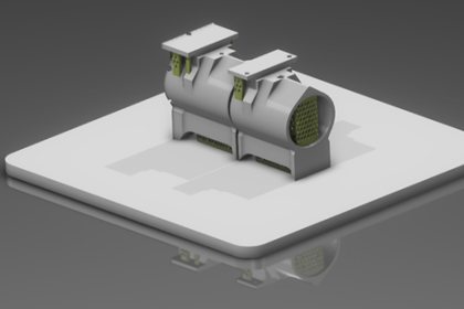
Oriented, nested and supported on the build tray
The best manufacturing direction is computed automatically to minimize supports, and parts are placed by automatic 2D or 3D nesting. Additive Manufacturing Engineer (A3D) does this for polymer parts in a dedicated printing wizard, and the powder bed roles do it ahead of slicing and scan paths, as on the 4 brackets here.
With integrated simulation
Predict stress and distortion
Powder Bed Machine Specialist (APX) adds the SIMULIA Distortion Checker, a guided assistant made for the additive programmer. It meshes the part, the supports and the build plate, applies the eigenstrain library stored on the machine, and simulates distortion and displacement on the computed laser path or on a pattern.
- 01Stress and displacementRead in color on the part as it grows from the plate.
- 02More process scenariosQuick virtual simulation lets the programmer try several before anything is printed.
- 03Supports optimization through simulationThe support structures are adjusted to the predicted distortion before the build.
Add, then cut
The additive result is the stock for NC machining
A part is deposited with Material Deposition Machine Programmer (AMD), or printed on a powder bed, then finished with the machining apps on the same platform. Dassault Systèmes call this digital continuity: from design to additive to NC machining on one model, so a design change reaches both programs.
- 01One setupA 3D NC machine is a hybrid resource: the deposition head lifts away and an end mill comes in on the same table.
- 02ISO code simulationThe finishing program is simulated as the posted code the controller reads.
- 03A 3D model for the next appThe build is the input for NC machining or wire EDM, where the support structures are removed.
What you buy
Licensed by roles
A role gives one user the apps for their job. 5 roles cover additive manufacturing on the 3DEXPERIENCE platform.
What do you print with?
What would you like to do in DELMIA?
Program additive machines
With integrated simulation
5 roles cover additive manufacturing.
Frequently Asked Questions
Which printing technologies does it cover?
Most polymer and metal printing techniques. Powder bed (SLS, SLM, EBM, DMLS, Multi Jet Fusion, binder jetting), directed energy deposition (laser cladding, LMD, LENS, wire deposition, WAAM), material extrusion (FDM and FFF, including composite and concrete), photo polymerization (SLA, DLP) and material jetting. Each role covers a family: Additive Manufacturing Engineer (A3D) the polymer and prototyping techniques, Powder Bed Machine Programmer (APB) and Powder Bed Machine Specialist (APX) powder bed, Material Deposition Machine Programmer (AMD) deposition and extrusion.
What separates the 2 powder bed roles?
Simulation. Powder Bed Machine Programmer (APB) and Powder Bed Machine Specialist (APX) both prepare the build: process reuse, orientation, nesting, supports, labels, slicing, scan paths and printer output. Powder Bed Machine Specialist (APX) adds the SIMULIA Distortion Checker, where the programmer predicts stress and distortion and tries more process scenarios before anything is printed. A shop chooses one of the two.
Will it write the file my printer reads?
The standards are supported: STL, AMF and 3MF, plus the slicing formats CLI and SLC on the powder bed roles. 3D printer code is written in the specific format of the powder bed printers Dassault Systèmes have integrated, each one selected as a virtual machine. Any other powder bed printer is reached through the Neutral Scan Path (NSP) format, which includes all the scan path information for a post-processor to convert to the printer format. We check your printer against this before quoting.
Why program the scan path when the printer can compute it?
Because the path is then yours and stays on record. The scan path, the supports, the rules and the printing parameters are saved with the part on the platform, so the same build can be repeated and the same scan path is available in the future for certification purposes. Dassault Systèmes single out aerospace and defense and life sciences for this. A known laser path is also what a precise process simulation needs.
Can it program a robot, a gantry or a concrete printer?
Yes, with Material Deposition Machine Programmer (AMD). Resources are a generic machine, a 3D NC machine or a robot, with gantry, rail and table accessories. A multi-brand robot library comes with its translators, reachability is validated as the path is written, and the output is direct robot language. The following curve activity suits composite and concrete, which is how a printed wall is programmed.
Does it work from the CAD model or from an STL?
From the exact geometry. Build preparation runs on the design model, from CATIA or from another CAD system, so the tessellation step and its deviations leave the process, and a design change updates the build through the revision check on the platform. An STL file is imported straight into a build layout when that is what a customer sends.
Resources
Articles, events and downloads from across the Dassault Systèmes portfolio.
Training on DELMIA
Official Dassault Systèmes courses, taught by certified instructors in person, at your offices or online.